Frank,
If we want to reduce wires through the hull perhaps we could hook these
rudder & motor
angle indicators into the linear actuator circuit. When the actuator is
moving it will relay
the position & when power is off to them perhaps there could be a
memory in the led circuit
that keeps the last position lit.
What do you think Jens? More work!
Alan
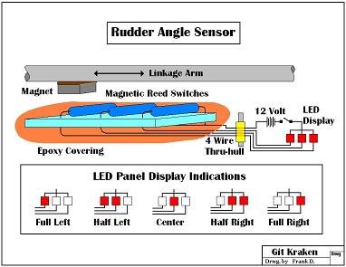
----- Original Message -----From: Alan JamesSent: Saturday, March 27, 2010 5:39 PMSubject: Re: [PSUBS-MAILIST] Rudder Indicator using 3 Reed RelaysFrankI've already pressure / water proofed the potentiometer.http://www.psubs.org/projects/1235435392/positionsensor/
All that needs doing is the potting of the wires when I attach them.I'm going to put a similar Perspex cover on the back of it as I've discovered that the ballinside is magnetic & I want to space it out a bit in case its mounted on a metal hull &the balls attraction to the hull competes with the magnet that moves it."WARNING" get the polarity of your magnet right so its pulling the ball around the potentiometer,not pushing it.This thing should work to thousands of feet, its super simple to do & you can have fine incrementsof movement indicated on it. Jens & I are working on the display unit which should be really cheap to makebut professional. The integrated circuit only costs a couple of bucks.Re your linear actuator; I think you could just use a long motorcycle suspension boot & take it the length of youractuator. This would save fibreglassing it, which is a pain on items that small.Alan----- Original Message -----From: ShellyDalg@aol.comSent: Saturday, March 27, 2010 2:13 PMSubject: Re: [PSUBS-MAILIST] Rudder Indicator using 3 Reed RelaysHi Jens and Vance. I like the different colors, making it simple to see left/right in the dark. Not being an electronics guy, I'm wondering what all the other devices located on the PC board are for in the Youtube video. Are these required to use logic to sense what an "illegal" position is and there by light up the "error" LED ?Here's a another little sketch of my concept for the "three reed" set-up. I didn't use any electronic parts 'cause I don't know what they would be used for. (Sorry, not too bright with that stuff. )Now as Vance said, if you desire to know more exactly where the rudder or dive plane is pointed you can add more LED's but of course that means more wires in each thru-hull.The potentiometer thing has only three wires for a full range of movement but if I understand Alan's description, it has a ball bearing running down the groove to make contact between the two electrical tracks.I've no clue how you would prevent such a device from getting squeezed. Even a tiny bit of compression would surely freeze that part. I'll wait and see if Alan gets a prototype together, and subjects it to a pressure test.Still, you gotta figure with one sensor for rudders, another for each dive plane, and possibly another for up/down vectoring on a nozzle, you're up to 4 thru-hulls and a BUNCH of wires.I kinda like Vance's idea of a strictly mechanical device with a hard cable and an indicator sitting just outside the window. Not much to go wrong there if it's lubricated. It can get pretty dark down deep so maybe a light would be needed to see the indicator unless you had cabin light shining out the window.Frank D. e to make contact between the two electrical tracks.I've no clue how you would prevent such a device from getting squeezed. Even a tiny bit of compression would surely freeze that part. I'll wait and see if Alan gets a prototype together, and subjects it to a pressure test.Still, you gotta figure with one sensor for rudders, another for each dive plane, and possibly another for up/down vectoring on a nozzle, you're up to 4 thru-hulls and a BUNCH of wires.I kinda like Vance's idea of a strictly mechanical device with a hard cable and an indicator sitting just outside the window. Not much to go wrong there if it's lubricated. It can get pretty dark down deep so maybe a light would be needed to see the indicator unless you had cabin light shining out the window.Frank D.