|
Hi Jens & Frank,
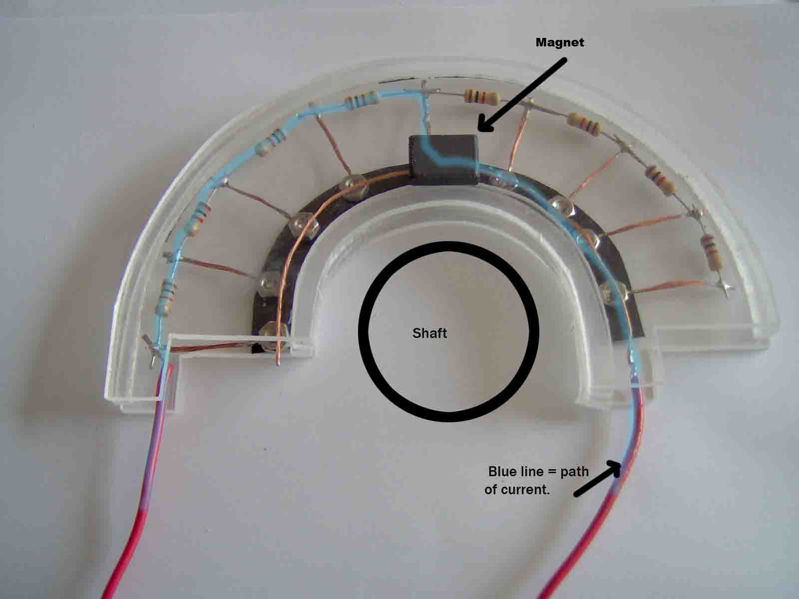
Attached is my "abandoned" homemade position
sensor. Its in its unrefined state & not glued together.
The idea is that there is a copper wire or copper
tape attached to the under side of the
lid of the acrylic housing. A magnet is attached to
an arm on the rotating shaft the motor is mounted on.
The magnet sweeps over the nuts which sit on a
fridge magnet material & lifts them into contact with the wire,
reducing the resistance by 1k on each segment of its transition; the difference in
resistance is picked up
by Jens unit in the sub, this lights
up LEDs accordingly.
A better way to do it would be, as someone
suggested, use reed switches which can cost less than $1-
each.
That way this could be made a lot less bulky by
pulling the resisters in closer to the switch mechanism.
One problem that Jens pointed out is that you
couldn't have a gap in between where the magnet moved off one
switch closing it & moving to the next &
opening it. This could be overcome by having a
long magnet that keeps
the previous contact closed momentarily. You would
have at times 2 contacts closed which would be OK going
from 10k resistance position down to 1k as the
current would take the path of least resistance. However going
back the other way it would give a slightly false
reading.
Am still ordering the membrane potentiometers
Frank, however you still have to encase them & linking 10 reed
switches & resisters together isn't too hard
& offers the ability to tailor make the unit to your
requirements.
Jens you talked about a memory for the last contact
position to overcome the "gap " problem. Is this difficult
to do.
Regards Alan
|
Attachment:
position sensor 001 copy.jpg
Description: JPEG image