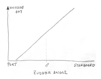
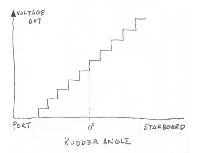
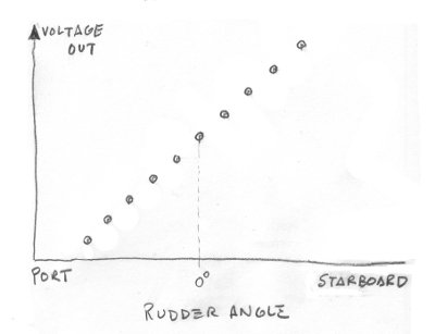
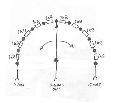
What I said in my previous mail about 'the signal should represent a
linear, variable (analog or discrete steps) voltage divider' should be
complemented with the following restriction: "it must also represent a
continuous (coherent) DC voltage (signal)".

Ref.: attached images [analog-signal.jpg/discrete-steps.jpg]

If I understand you correctly, Alan, then your device (throw switch) will
produce a non-coherent series of voltage levels (signals) that will cause
a lot of "black holes", i.e. no LED lit on the rudder angle indicator
whenever the rudder angle doesn't coincide with the fixed positions of the
contact points on the throw switch itself.

Ref.: attached images [isolated-values.jpg/SP11T-switch.jpg]

Therefore, to use such a switch, we will have to include some "memory" to
the existing circuit to ensure that the last LED remains lit until a new
position on the switch is reached (i.e new signal update).

What do you think, Alan?

The current version of my Rudder Angle Indicator can be viewed/downloaded
here:

ftp://ftp.artematrix.org/instrumentation/rudder_angle_indicator/LM3914_RAI_V1.jpg

The LM3914 data sheet can be viewed/downloaded here:

ftp://ftp.artematrix.org/instrumentation/rudder_angle_indicator/LM3914.pdf

Best regards,
Jens Laland
Attachment:
analog-signal.jpg
Description: JPEG image
Attachment:
discrete-steps.jpg
Description: JPEG image
Attachment:
isolated-values.jpg
Description: JPEG image
Attachment:
SP11T-switch.jpg
Description: JPEG image