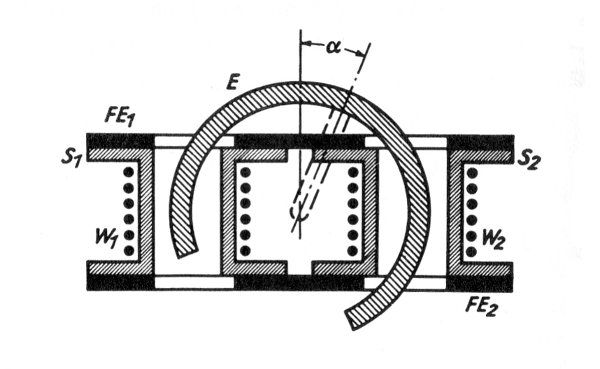
The 'signal source' can be a potentiometer or a 10-throw switch, etc. The
main issue is that it represents a linear, variable (analog or discrete
steps) voltage divider (and I believe the circuit should handle the supply
voltage on board).

Tomorrow, when back in the workshop, I'll put together a preliminary
circuit diagram and part list, and make that available.

Personally, I want to try out a simple, homemade inductive angle sensor
instead of a pot-meter, as I think it would be a lot easier to waterproof
a pair of coils [ref. attached image].

However, if that will work, then I would also need to handle AC signals,
which again requires a different circuits.

There was a few other questions asked, but I'll tend to those to morrow.

Best regards,
Jens Laland
Attachment:
induction-sensor.jpg
Description: JPEG image